Skip to content
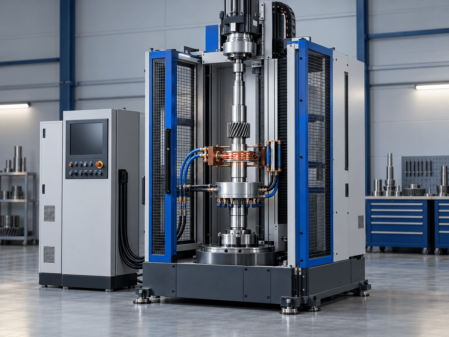
Illustrative product concept of a CNC induction hardening cell with a shaft, gear, induction coil and quench station

Illustrative product concept; final configuration and specifications are confirmed during engineering review.

Material & process

Share the workpiece alloy, dimensions and target process so the equipment route can be reviewed.

Output & duty

Define batch or throughput needs, operating schedule and required temperature or treatment result.

Site & utilities

Confirm available power, cooling, layout and destination-market requirements before final specification.

Induction Heat Treatment Systems · FL-IH-HRD

CNC Induction Hardening and Tempering Machine for Shafts and Gears

CNC induction hardening configurations for shafts, gears, rails and other steel parts, engineered around part geometry, alloy, target case depth and line requirements.

  • Part-specific coil and quench arrangement
  • Scan or single-shot cell concepts for engineering review
  • Workholding and handling planned around the component drawing
  • Quench-medium and delivery approach selected for the process route
  • Optional automation, controls and tempering stage defined in the proposal
Part family
Shafts, gears, rails and other drawing-based steel components
Process route
Scan or single-shot arrangement, subject to part geometry and process review
Engineering inputs
Drawing, steel grade, treated zones, target hardness and case-depth requirement
Cell configuration
Coil, rotation, traverse, quench and handling selected for the part and production flow
Power and frequency
Selected after review of material, geometry, heating cycle and process-trial results
Automation and records
Control, handling and process-data scope confirmed in the technical proposal
Tempering
Optional process stage, confirmed against the required metallurgical route

Product Details

Induction hardening heats a selected surface area and applies a quench to develop the requested hardened layer while retaining the core properties required by the part. The process window depends on the steel grade, geometry, coil design, frequency, power, scan strategy and quench medium; it is reviewed against the customer's drawing and target properties.

Possible machine layouts include scan hardening for longer components and single-shot stations for suitable part geometries. Rotation, traverse, coil and quench arrangements are selected around the workpiece and the required production flow rather than assumed from a generic machine layout.

For a technical review, provide part drawings, material and hardness requirements, target case depth, treated zones, expected output and available utilities. Working envelope, power supply, automation and any tempering stage are confirmed after engineering review and process trials where required.
FL-IH-QT

Induction Quenching & Tempering Line

In-line hardening plus tempering in a single continuous pass — for steel strand, PC bar, drill rod, grinding rod and tube, with per-zone temperature control.

Read More →
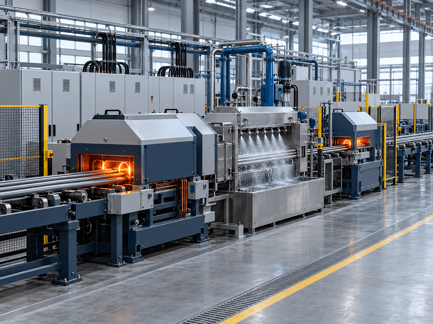
Continuous induction quenching, controlled water spray and tempering line for steel bar and strand

Illustrative product concept; final configuration is confirmed during engineering review.

Tell us what your process needs.

Share the material or part, target output or treatment result, operating schedule and site utilities. Our engineers can review the equipment configuration and quotation scope against your application.